How to Deliver Odors
Neuroscience
Olfaction
Methods
Technical specification of independent-channel vs. serial olfactometer architectures and pneumatic constraints.
Keywords
MFC, odor, valve, olfactometer
Odor Delivery Strategies
Traditional olfactometry often relies on sequential delivery, which limits the complexity of the olfactory stimuli. This document introduces two alternative strategies for delivering odors, each with distinct mechanical advantages and technical trade-offs.
Legacy Serial Olfactometer Strategy
The legacy strategy is characterized by a shared manifold architecture where odors are presented sequentially. This approach is optimized for single-odor stability.
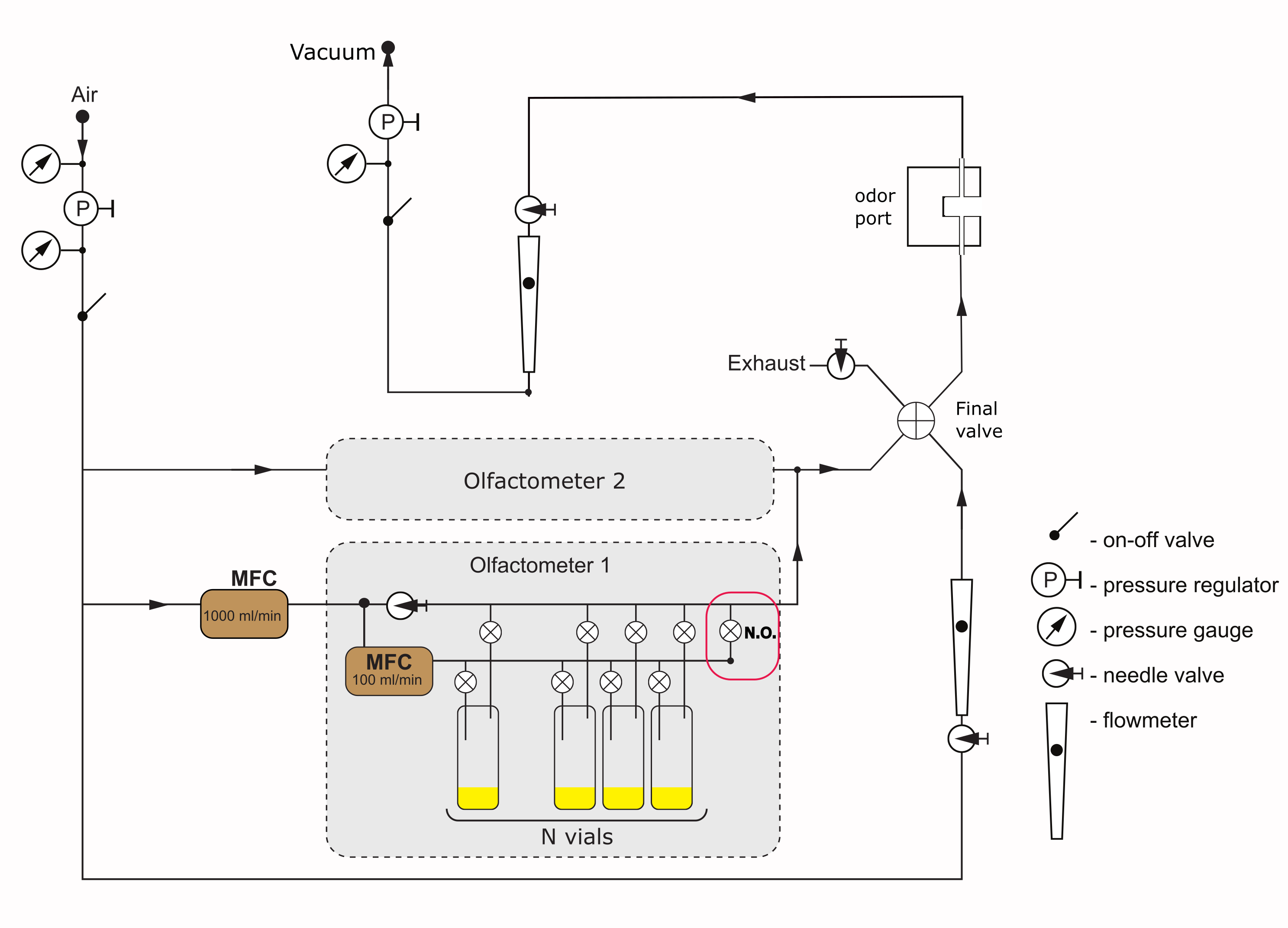
Operational Logic
- Capacity: Each olfactometer cassette is designed to present only one odor at a time.
- Bypass Mechanism: Each cassette features a Normally Open (N.O.) valve at the end of the manifold.
- Standby State: When no odor is being delivered, the N.O. valve remains open, allowing air to bypass the odor vials.
- Odor Delivery State: To initiate delivery, the N.O. valve closes, and the valves flanking a specific vial switch on.
- Pressure Dynamics: Since only one path is active at any time, the pressure load on the source remains constant.
- Final Valve Management: A dual 3-way final valve toggles between a clean air line and the cassette output.
Important
This design does not support opening of multiple vials in one olfactometer.
Independent-Channel Parallel Strategy
The parallel strategy utilizes an independent architecture, allowing for complex mixtures and individual flow control for every channel.
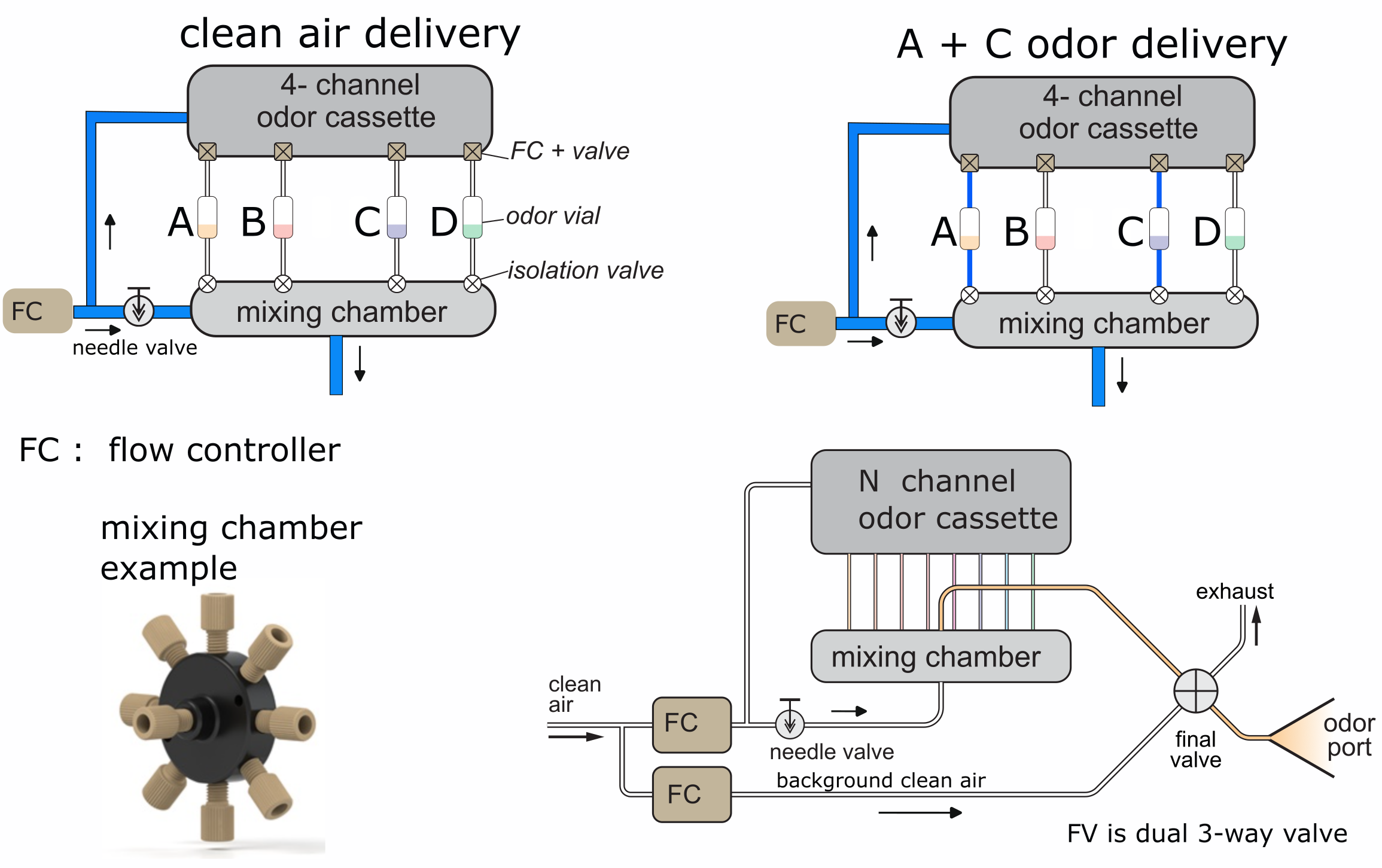
Component Description and Flow
- Independent Flow Controllers (FC): Every odor line (A, B, C, D) is equipped with its own dedicated flow controller.
- Dual Isolation Valves: Each odor vial is isolated by valves both before and after the vial.
- Mixing Chamber: A specialized hub collects and blends the output from any combination of active channels.
- Dual 3-Way Final Valve (FV): This valve manages the transition between the odor port and the exhaust.
WarningCritical Pneumatic Constraint
- Vial Input Demand: Opening multiple vials simultaneously creates cumulative carrier gas demand.
- Pressure Stability: Each independent channel requires a “stiff” pressure supply.
- Scaling Limit: The system requires high enough input pressure to maintain independent flow integrity across all active lines.
Comparative Strategy Analysis
| Feature | Legacy Serial | Parallel Independent |
|---|---|---|
| Mixing Capability | 1 odor per cassette | Up to 4 odors simultaneously |
| Flow Control | Shared MFC for manifold | Dedicated FC per line |
| Vial Isolation | Shared bypass via N.O. valve | Independent valves per vial |
| Pressure Load | Constant — low demand | Variable — high demand per vial |